MKC TOOLSJet 15-JMD Mill/Drill TachHere are details of how I mounted a Trexon SFM tachometer (mkctools.com) with optical sensor on my Jet JMD-15 mill/drill. 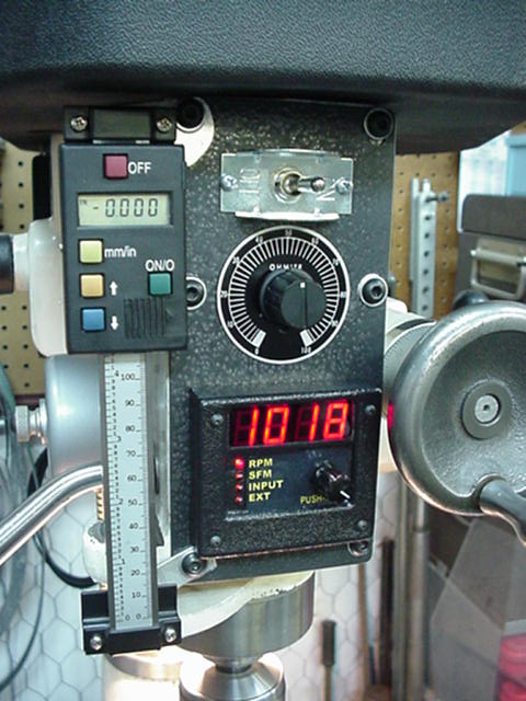
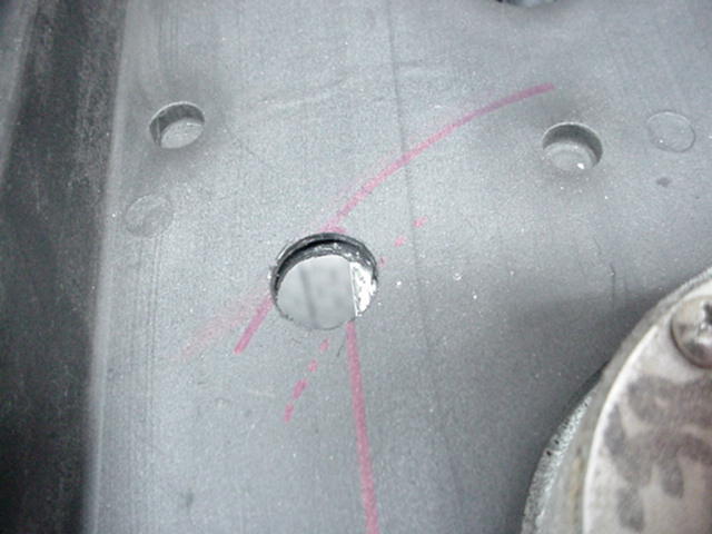
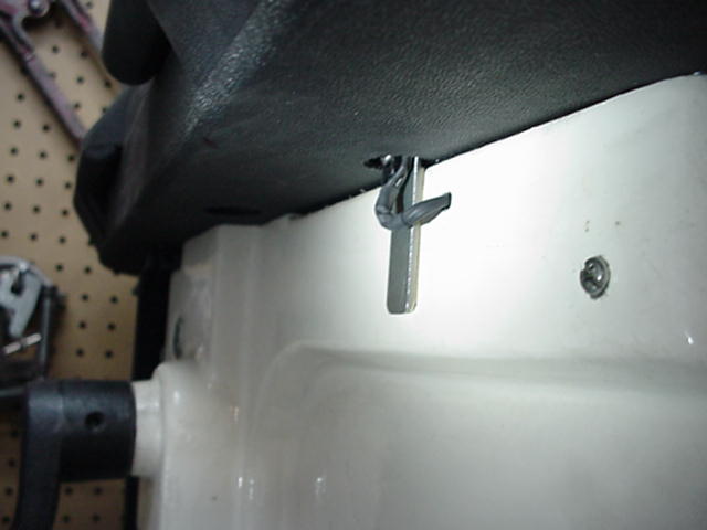
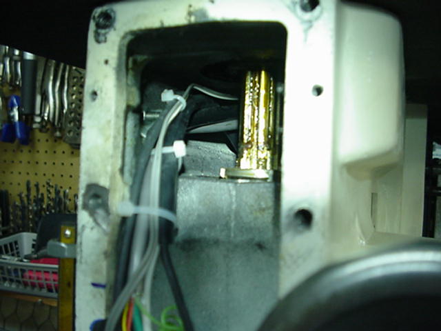
I decided to use the bottom side of the pulley for the sensor reading surface for a clean looking installation. Before removing the spindle pulley I marked the track of the outside edge of the pulley on the belt guard where the sensor would be mounted. Then I removed the pulley with a puller. It was relatively easy because the pulley mounts on a tapered portion of the spindle and has no key. After removing the pulley I sighted down the side of the head and marked the belt guard for the sensor position. The dotted line marks the inside edge of the bottom pulley flange and the X marks where the sensor nose will be positioned. I drilled a 3/4" hole throught the belt guard (there are two layers about 1/2" apart) centered on the X. You can see the edge of the head casting through the hole. This is just right for mounting sensor to the side of the head. 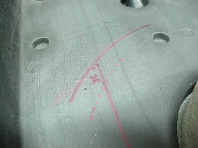
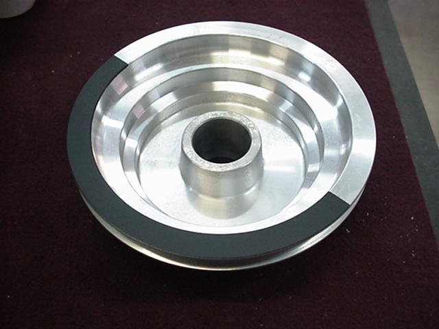
Next I masked and painted half the pulley flange flat black and reinstalled the pulley. 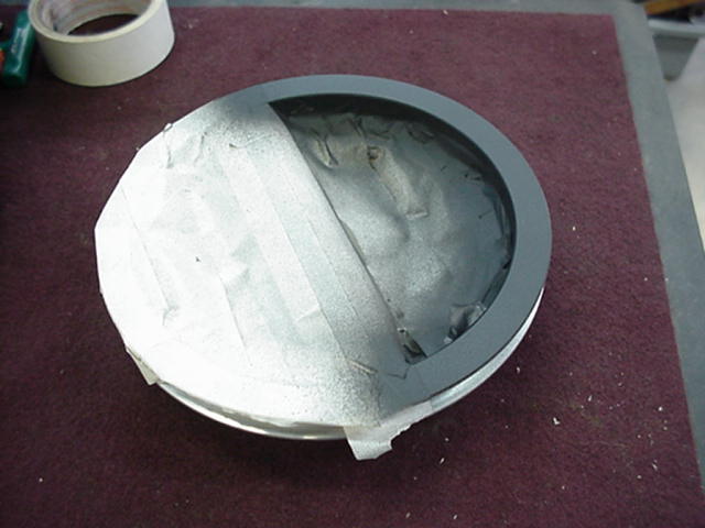
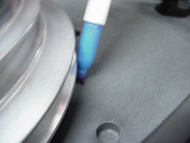
To mount the sensor I cut a piece of 16 ga. steel plate 1/2" x 2" and drilled and tapped two 4 x 40 holes about 3/8" apart. Double faced foam tape can be used here but I didn't want to take a chance on it. I did use it to mount the plate to the side of the headstock. Positioning here is key. The sensor needs to be 1/8" from the surface being read. I placed the sensor in the hole until it hit the pulley and made a mark at the bottom end of the plate. Then lowered the plate 1/8" and made another mark. Then I peeled the backing off the foam tape and stuck it to the head lined up with the lower mark. It worked perfect the first time I turned it on. The spec for sensor spacing is .1 to .2" so 1/8" is near optimum. The tach board has a sensor sensitivity adjustment if needed. I put heat shrink on the sensor wiring and drilled a 3/16" hole to route it inside the head. 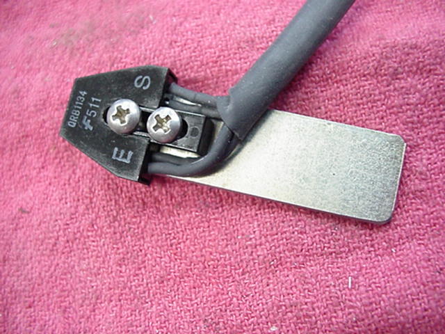
The sensor wiring and 9 volt power for the tach as well as the dc motor wiring and work light power were routed along the same path as the power to the original switch and tied off to keep them clear of the spline shaft. I had just made a new front panel plate for the dc motor controls and mounted the tachometer on the front of it. The tach board was a little too wide to mount behind the panel as usual. I have the belts currently set on 1-6 which would have been 730 rpm with the original 1725 rpm motor. It now runs 100 to 2000 rpm. All in all it turned out to be a very nice installation and everything works great. 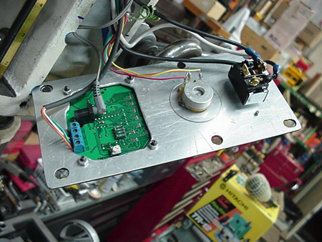
Contact by Email skip@mkctools.com Or Call 817-319-2297 --- MKC Tools Home |