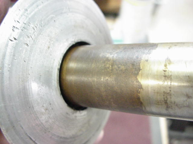
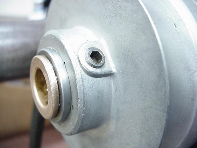
MKC TOOLS10ER Speed Changer SetupRead the instructions carefully and it will answer many of your questions. After 50+ years there may be additions steps needed to get the speed changer back in operating condition. Note: When using the speed changer on the 10E/ER the motor pulley must be reversed from its normal direct drive orientation. The large 4" step must be toward the motor and in line with the 4" step on the headstock pulley. Start this procedure with the motor raised to max height. First of all the condition of the pulley assembly needs to be checked. The "floating sheave" is the center portion of the assembly that should slide easily back and forth between the two outer "fixed sheaves". It is an aluminum part with a steel sleeve base that rides on the steel center hub. Many of these, if they have sat unused and not maintained will be rusty and possibly frozen and need to be cleaned up before use. Sometimes they can be freed up by soaking in penetrating oil but it is much better to disassemble it and clean off the rust from the hub and inside the floating sheave. Then apply a coat of light grease and reassemble. 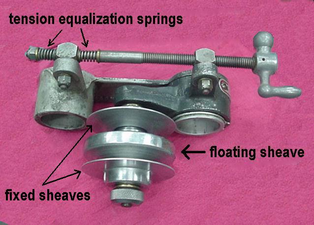
 Next, the fixed sheaves should be set for the belts being used. All 1/2"
4L type belts are not the same width and/or height and in order to get
the best performance from the speed changer the fixed sheaves need to
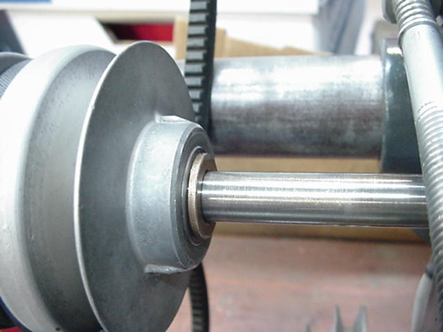
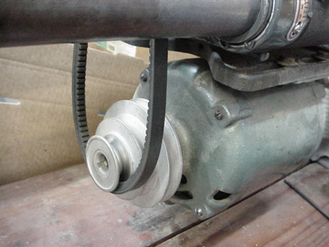
be adjusted properly. As seen in the photos below, set one fixed sheave
even with the end of the steel hub and tighten the set screw firmly.
Set the other fixed sheave in from the end of the steel hub about 1/8"
and lightly tighten the set screw. Using one belt only, slide the floating
sheave to one side and press the belt down into the groove. Hold the belt
straight (or as I do, turn the belt inside out) so you can see though
between the bottom of the belt and the bottom of the groove. You want
the belt to go as far down into the groove as possible to get full speed
range from the changer BUT, you do not want it to bottom out on the base
of the floating sheave. This will cause belt slipping and can cause the
floating sheave to spin on the center hub causing undue wear to the assembly.
I like to have close to but not less than 1/16" clearance under the belt.
Gradually move this fixed sheave out until you get the desired clearance.
I recommend checking this annually to make sure belt stretching or belt
and pulley wear have not allowed the belt to bottom out.
Next, the fixed sheaves should be set for the belts being used. All 1/2"
4L type belts are not the same width and/or height and in order to get
the best performance from the speed changer the fixed sheaves need to
be adjusted properly. As seen in the photos below, set one fixed sheave
even with the end of the steel hub and tighten the set screw firmly.
Set the other fixed sheave in from the end of the steel hub about 1/8"
and lightly tighten the set screw. Using one belt only, slide the floating
sheave to one side and press the belt down into the groove. Hold the belt
straight (or as I do, turn the belt inside out) so you can see though
between the bottom of the belt and the bottom of the groove. You want
the belt to go as far down into the groove as possible to get full speed
range from the changer BUT, you do not want it to bottom out on the base
of the floating sheave. This will cause belt slipping and can cause the
floating sheave to spin on the center hub causing undue wear to the assembly.
I like to have close to but not less than 1/16" clearance under the belt.
Gradually move this fixed sheave out until you get the desired clearance.
I recommend checking this annually to make sure belt stretching or belt
and pulley wear have not allowed the belt to bottom out.
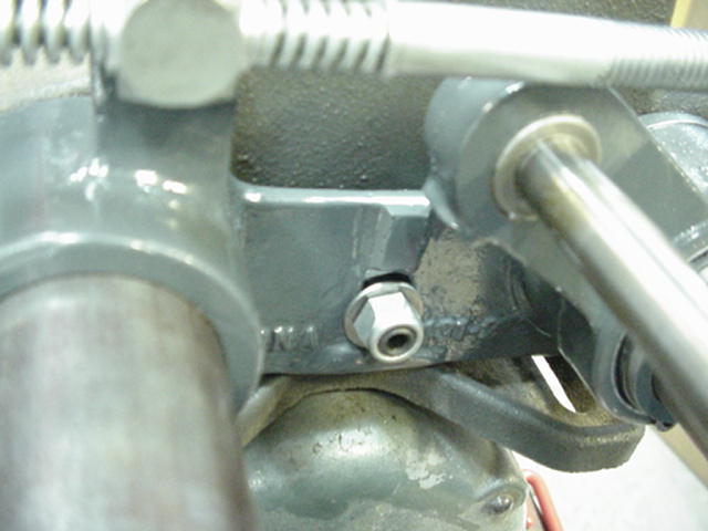
To permit the speed changer assembly to slide easily on the way tube with the headstock, a thick washer should be placed on the mounting set screw between the headstock and the speed changer casting. Another washer and then the nut will go on the outside of the casting. By pushing and pulling on the center of the speed changer the tendency to bind on the way tubes is greatly reduced. It also helps to keep the way tubes treated with Johnson's paste wax. 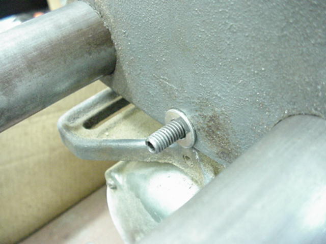
Since the belts can't be mounted onto the speed changer pulley when it is mounted on the machine, you must put the belts in the grooves of the pulley and slide it onto the shaft as shown in the left photo below. The long belt will go inboard so that it will line up with the 4" step on the headstock or motor pulley and the short belt outboard for the 2" steps. Now for adjusting the belt tension: Raise the pulley assembly so that you can roll the desired belt over the headstock pulley step. This will be the long belt on the 4" step for low range or the short belt on the 2" step for high range. Set the other belt wedged between the way tubes so that it is suspended clear of the speed changer pulley groove as in the right photo below. 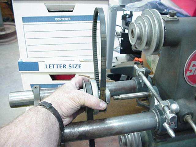
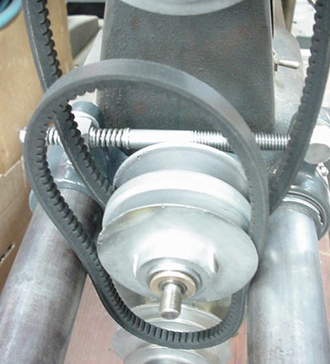
At this point you want the floating sheave to slide all the way to one side so the belt on the headstock pulley will go all the way down into the groove. Now crank the pulley assembly down to tension the upper belt. (left photo below) When the belt starts to get tight, watch the springs on the rear end of the crank rod. Neither of these springs should ever be fully compressed. A compressed spring is an indication of too much tension on one belt or the other. The springs are there to equalize the tension on the two belts after changing speeds. Once the upper belt is properly tensioned then you can roll the other belt onto the motor pulley. Then lower the motor to adjust the tension of the belt, also watching the springs. You don't want too much tension on the belts. That is why the raw edged cogged belts are so nice for the speed changer. They have much more traction with less tension than the original type belts plus they are much more flexible and therefore more effecient. Lock down the motor mount set screws firmly. Never use the weight of the motor for belt tension whether you use the speed changer or not. Run the chager up and down through its range and then stop in the middle of the range. Both belts should always have the same tension. If not, something is wrong. Go back through the procedure again to make sure you have everything set correctly. Your speed changer should now be ready to run. Please let me know if you have questions or suggestions for improving this procedure. 
Contact by Email skip@mkctools.com Or Call 817-319-2297 --- MKC Tools Home |